Category Archives: Amateur Radio

Delay Tolerant Networking over AX.25 & QSLs

I wrote in January that I had done some testing of Darren, G0HWW’s DTN over AX25 (also know as Packet Radio) Implementation. At the time we really only wanted to see if it worked. Since then I have been quite busy in my day job, and not had a chance to really do any more testing up until recently.

In the last few weeks had some free evenings and devoted it to testing the Darren’t DTN implementation against ‘raw’ AX25 connections with different AX25 window sizes from 1 – 7. I used a test file size of 9744 bytes (a NASA format keplerian element set that was handy) over at 1200bps AX25 link.

For the raw AX25 test, I connected from one node to another over and had the test file waiting for me in an email (using axmail). I recorded the wall clock time from when I pressed return until the command prompt was returned.

For the DTN test, I used the dtncp command to send the file and I started recording from when I pressed return on the command line. Obviously there is a problem there in that the AX25 test has to transmit the command before it can receive anything, whereas dtncp immediately starts transmitting, but as I only wanted to get a ‘feel’ for the figures, I think it will suffice. Several runs of each later (to get average figures) we have:

Window Size “Raw” AX25 (seconds) DTN over AX25 (seconds) Delta (seconds)
1 110.67 121.33 10.67
2 90.33 106 15.67
3 84.67 101 16.33
4 81.67 97.67 16
5 79 95.67 16.67
6 78 91.67 13.67
7 77 108.33 31.33

I’m not an AX25 expert by any stretch of the imagination, so we had several false starts trying to get working settings for the various timers that are part of the AX25 implementation. None of them were set to ‘optimum’ but really I just increased T1 and T2 in line with the Window parameter until it worked reliably.

Several things surprised us. Firstly, Darren’s implementation is not as bad, performance wise, as we thought it would be. At the moment, no effort been made to streamline the implementation but it is designed to be highly robust in the event of data transmission errors. Secondly, all data was transferred successfully on every occasion, always good :). Also, on average, the overhead (if we ignore the window of 1 and window of 7), is between approximately 17% and 21%. The figures for the Window set to 1 (above) is a special case in that it forces an almost ’round-robin’ transmit cycle on the two participating stations. Setting it to 7 seemed to trigger a bug, but we don’t know where exactly. In fact the picture is much worse than that. 1 in every three runs took almost 5 minutes to complete as the two stations got completely out of sync AND it looks like Darren’s code (or the kernel) wasn’t honouring the window of 7. In reality though, it would be seldom that one would attempt to use a window size of 5-7 on a shared frequency due to the likelihood of being ‘trod on’ by another station.

All that said, it’s pretty reliable. If your are interested in giving it a try, email Darren, his details are at the bottom of this page, describing his implementation.

Now, back to writing QSL Cards. Shamefully, I’m several years behind.
Front

K3 #2184 (part 2)

It started raining again Sunday afternoon, so a perfect opportunity to resume construction 😉

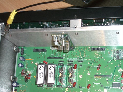
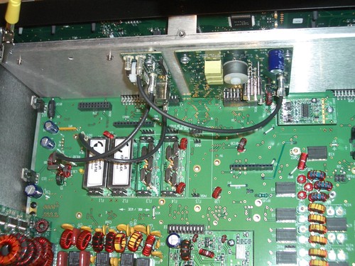
First, attach the DSP Board to the back of the front panel.

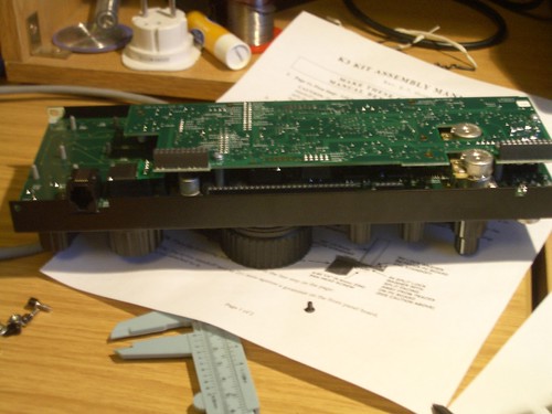
DSP Board Added - 1

DSP Board Added - 2

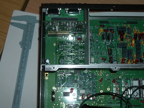
Attach the front panel to the main chassis.

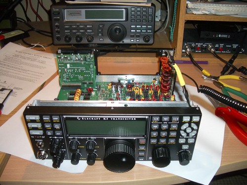
Front Panel Attached to Chassis - 1

Initial power on test, fortunately no smoke escaped!

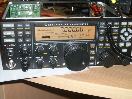
Initial power on test.

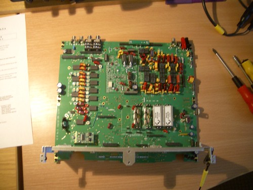
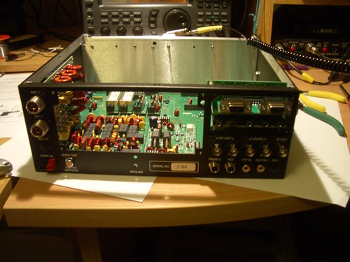
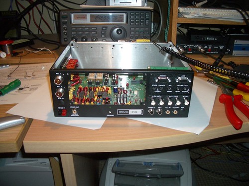
Oscillator board installation (you can see the filters on the main RF board)
KREF3 Oscillator Board

Synthesiser board installation. This (along with the oscillator board above) was the most difficult board to install, requiring lots of patience as I kept dropping the washers into the chassis.

Synthesizer Board

Power Amplifier Shield

KPA3 Shield

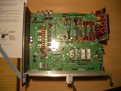
General coverage Receive filters, Noise Blanker, and Lithium Ion Battery.

KBPF3 General Coverage Receiver Installed

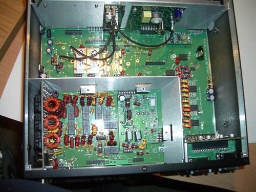
Forgot to take a picture of the 100W PA going in. All built now, just needs calibration.

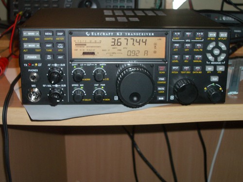
K3 #2184 is alive!

Pretty much everything checked out ok. I still have to calibrate the TXCO, though as it is, it is probably more than adequate for my needs. Now I just need to get time to get on the air.

Thank you Elecraft.

K3 #2184 (part 1)

It arrived yesterday, but I was too tired to do anything with it last night. When I opened the box this morning, I instantly thought I had made a big mistake getting it in kit form. Lots of little bags with more little components all labelled very very carefully.

I got some courage up after lunch and pulled it all out of the box, everything I ordered seemed to be present, so I took a deep breath and opened the first anti-static bag.

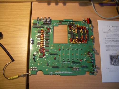
Main RF PCB

It progressed rapidly after that.
Filters and LPA Installed

Front Shield, Left Side Installed & KAT3 Installed

KIO3 Installed

K3IO Installed

KIO3 Digital IO Installed

IMGP3411.jpg

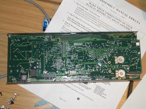
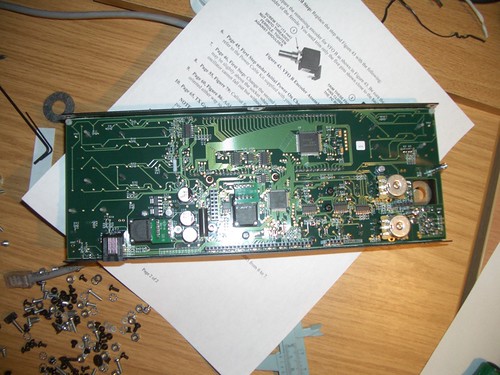
Rear of Front Panel

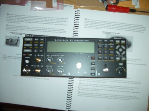
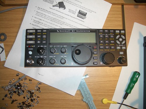
Front Panel with Knobs and plastic covers Installed

Enough for today. I only panicked once (when I couldn’t find the 2-56 1/4″ screws for the LCD standoffs), and only made two mistakes that I know of (so far) which happened on KIO3. Many thanks to Mario, Marina, Dina, Patricia, Sharron and Ellison for your attention to detail while packing.

Magic Smoke!

Unfortunately I accidentally released the magic smoke (sorry Scott, didn’t mean to hurt it) from the venerable OT-1 that I was using to measure my PV array (see my earlier post). So I’ve parked that experiment for a while. As we get closer to the solstice, its amazing (to me) to watch the amount of ‘sun hours’ available to the panel decrease. I’ll have to begin negotiations with SWMBO for a better location for them next year.

DTN over AX25 – Update.

Dissapointingly it has taken far to long to get back to this (see my earlier post), but recently Darren and I managed to be both online over the same few days to organise some testing. The infrastructure has changed slightly, in that the testing is now taking place through an AX25 Digipeater on a 1200bps Packet Channel, with the nodes being approximately 32Km distant from one another.

Both machines were Ubuntu 8.04, with kernel 2.6.17 on my end, 2.6.24 on the far end, latest ax25 utilities and tools.

My end was used to bring up the link every time (The far end has no /proc/ax25, so I can’t sent the ax25 parameters remotely, I’ve to change/rebuild the kernel afaik)

Through the digi we used the following settings when setting up the kiss ports. Txdelay of 150ms, paclen of 255, maxframe set to 1.

We quite quickly identified a problem with ‘chattyness’ (the locals got upset), and Darren did some re-work. Since then its performing much better, and the locals are much happier. I was away for a bit and Darren has updated the code some more, so more testing for me I think.

Given that I’m looking at this from an Emcomm/AREN point of view, I’m really pleased with how its progressed so far, and I think Darren may even be considering sending the code ‘upstream’.

./configure ; make; sudo make install

PV Measurement

I’m still going through the various items in the house, trying to get average usage profiles is quite difficult, so far the biggest hog is the Ubuntu Server I have running under the desk, so I might have to re-visit my choice of machine in the future.

Something I’ve wanted to do ever since I installed the PV Panels was to get some data on them. I’ve started it at least, here (login required) you can see some data. The top graph is the air temperature in the office. The second is the battery bank voltage as seen at the charge controller. The third is not yet connected, but I’m hoping to get a current measurement from the panels as well over the next few days.

The device doing the measurement is an OT1 (discontinued) from Argent Data Systems. The radio is a Yaesu FT-1500M (also discontinued) with a transmit power set to 5 Watts. I had to make a minor modification to the OT1. The potential divider circuit is set-up for measuring up to 15 Volts, I had to change one resistor to allow measurement up to 30Volts.